Range Extenders FAQ
- Range Extender system structure
- Range Extender installation
- How to control PoCXP on CoaXPress extender over fiber
Range Extender system structure
Regardless of whether you use a CLHS or CoaXPress Range Extender, the basic system structure remains the same.
The Range Extender system consists of one or two converter units:
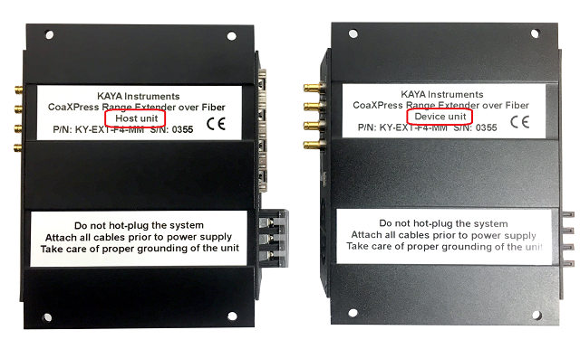
- Device unit
Connects to the camera and provides power (PoCXP via the CoaXPress connection). - Host unit
Connects to the Frame Grabber
Each unit can be used as a standalone solution, depending on the device configuration and connection topology.
Although the two units appear similar, they are constructed differently and serve distinct roles. Incorrect connectivity configuration may result in partial functionality or complete system failure.
Unit identification
- A label located at the back of each CoaXPress Range Extender unit will help identify the unit.

- An additional option is to access the unit using a USB cable and use the "status".
The instructions for connecting to the Range Extender can be found in the Firmware Update section.
For more information on system installation and available configurations, please review section "Installation procedure" of the user manual
Range Extender installation
Depending on the unit part number you can refer to our documentation:
- Camera Link compatible Range Extender over Fiber
- KY-EXT-CL: user manual, data sheet
- KY-CL2F-D — Device unit: firmware update
- KY-CL2F-H — Host unit: firmware update
- KY-EXT-CL: user manual, data sheet
- CoaXPress Range Extender over Fiber
- KY-FEXT: user manual, data sheet, firmware update
- KY-FEXT-D — Device unit
- KY-FEXT-H — Host unit
- KY-FEXT: user manual, data sheet, firmware update
- CoaXPress Range Extender over Coax
- KY-FEXT6G: user manual, data sheet, firmware update
- CoaXPress v2.1 Range Extender over Fiber
- KY-FEXT-II: user manual, data sheet
- KY-FEXT-II-D — Device unit: firmware update
- KY-FEXT-II-H — Host unit: firmware update
- KY-FEXT-II: user manual, data sheet
After connecting USB cable to the PC and extender, restart the power of the extender and check again the status
Connection rules
While using the CoaXPress Range Extender, please follow these rules:
- Maintain the correct connection topology by connecting channels numerically (CH0 = CH0, CH1 = CH1, CH2 = CH2, etc.).
- Do not connect fiber cables to the SFP modules unless an active CoaXPress link is connected, as this can seriously impact performance.
How to control PoCXP on CoaXPress extender over fiber
The PoCXP of the CoaXPress extender over fiber can be controlled by a CoaXPress Frame Grabber. To control the PoCXP, register 0x1000 should be written as BigEndian value, for each port individually, with one of the following options:
- 0 - PoCXP Off (always Off)
- 1 - PoCXP Auto (turn On when a camera is physically connected on a specific link)
- 2 - PoCXP force On (always On)
Here an example of PoCXP control register 0x1000 using Vision Point API:
2
3
4
5
6
7
8
9
10
11
12
13
14
15
16
17
18
19
20
21
22
23
24
25
26
27
28
29
30
31
32
33
34
35
36
37
38
39
40
41
42
43
{
POCXP_OFF = 0,
POCXP_AUTO = 0x01000000,
POCXP_ON = 0x02000000,
}POCXP_REMOTE_CONTROL;
#include "KYFGLib.h"
#include <stdio.h>
// ==========================================
int main()
{
int detectedDevices = 0;
KY_DeviceScan(&detectedDevices);
FGHANDLE fgHandle = KYFG_Open(0);
if (fgHandle == -1)
{
printf("Bad connection to grabber\n\r");
getchar();
}
else
{
printf("Good connection to grabber 0x%x\n\r", fgHandle);
}
static const uint64_t POCXP_REMOTE_CONTROL_ADDR = 0x1000;
for(int fgPhysicalLink = 0; fgPhysicalLink < 4; ++fgPhysicalLink)
{
KYFG_WritePortReg(fgHandle, fgPhysicalLink ,POCXP_REMOTE_CONTROL_ADDR, POCXP_OFF);
}
Sleep(1000);
for(int fgPhysicalLink = 0; fgPhysicalLink < 4; ++fgPhysicalLink)
{
KYFG_WritePortReg(fgHandle, fgPhysicalLink ,POCXP_REMOTE_CONTROL_ADDR, POCXP_AUTO);
}
KYFG_Close(fgHandle);
return 0;
}